
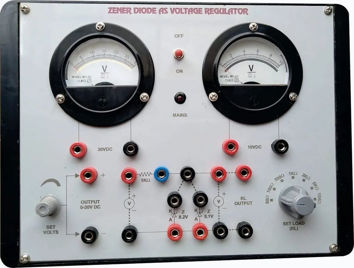
Zener Diode Characteristics & Voltage Stabilization.
Description
Zener Diode Characteristics & Voltage Stabilization refers to the study of a Zener diode’s V-I (voltage–current) behavior in both forward and reverse bias, and its essential function as a voltage stabilizer or regulator in electronic circuits.
Zener Diode Characteristics
Forward Bias: In this mode, a Zener diode behaves like an ordinary p-n junction diode, conducting significant current when the forward voltage exceeds its threshold (typically about 0.7 V for silicon diodes).
Reverse Bias (Zener Region): Unlike a regular diode, a Zener diode conducts in reverse once the applied voltage reaches the highly specific “Zener voltage” (Vz). At this point, the diode enters breakdown and maintains a nearly constant voltage across itself despite further increases in reverse current, thanks to its heavy doping and specialized construction.
Voltage Stabilization (Voltage Regulation)
Placed in reverse bias and parallel with a load, the Zener diode clamps the voltage across itself to the Zener voltage, even when supply voltage or load current fluctuates.
A series resistor limits current, and the stabilized voltage across the diode is used as the regulated supply for sensitive circuit components.
The diode only stabilizes voltage when the current through it stays within its rated minimum and maximum values; operation outside this range may compromise regulation or damage the device.
Applications
Zener diodes are widely used as shunt regulators, reference voltage sources, and over-voltage protection elements in analog and digital circuits, due to their stable, predictable breakdown voltages and ability to maintain constant voltage under load variations.
This combination of characteristic analysis and voltage regulation capability makes the Zener diode fundamental to power supply and signal conditioning circuits in electronics.
Specifications
| Model No. | N-EL035 |
|---|


