Thank you for writing to us. One of our executive will reach back to you through your submitted medium. In case there’s an urgency, feel free to connect over WhatsApp for faster response.
Prefer calling? Dial +918048036175 (International callers) or 08048036175 (Indian callers).
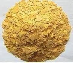
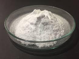
Egg albumen flakes are dehydrated forms of egg white, processed for laboratory and industrial use. They are valued for their high protein purity, ease of solubility, and stability for applications like electrophoresis, cell culture media, and microscopy.
Preparation and Properties
Sourced from pasteurized, separated egg whites that are dried and ground into flakes or powder.
The flakes dissolve readily in water, forming clear solutions suitable for biological adhesives or protein analysis.
Commercial flakes are typically additive-free, offering reliable results in scientific experiments.
Laboratory Usage
Egg albumen flakes are optimal for preparing adhesive solutions for microscopy, slide mounting, or as protein standards in analytical tests.
For microscopy, the albumen can be rehydrated and spread onto slides or used to prepare colloidal solutions for demonstration and practical experiments.
Quality control involves drying the albumen, grinding, passing through fine sieves, and packing in sealed containers.
Egg albumen flakes provide a convenient and reproducible source of protein for diverse laboratory, educational, and research applications.
Egg albumen flakes are dehydrated egg white, processed into flake form for laboratory, research, and industrial uses rather than food applications.
Properties and Composition
Derived from high-grade, pasteurized chicken egg whites.
Major protein: Ovalbumin; also contains ovotransferrin, ovomucoid, and other minor proteins.
Flakes are off-white or light yellow, dissolve easily in water, and are free from additives.
Laboratory Uses
Employed in electrophoresis, protein standard preparations, cell culture, and as a protein supplement in culture media.
Used for making biological adhesives to help attach sections or samples to microscope slides.
Suitable for preparing colloidal dispersions and as a biodegradable matrix in experimental drug delivery systems.
Egg albumen flakes offer reliable protein content and solubility, making them a convenient standard for various biochemical and microscopic techniques.
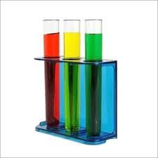
EDTA Solution N/50 (0.02N) is a standardized aqueous solution of disodium ethylenediaminetetraacetate, primarily used as a titrant in complexometric analysis, especially for determining concentrations of metal ions like calcium and magnesium in water hardness titrations.
Properties
Concentration: 0.02N (N/50), which equals approximately 0.005M.
Appearance: Clear, colorless, odorless liquid.
Physical state: Liquid at room temperature.
Laboratory Use
Used for volumetric (complexometric) analysis due to its ability to form stable chelates with metal ions.
Commonly paired with indicators like Eriochrome Black T for EDTA titrations of water hardness.
Analytical Grade preparation for accurate and reproducible results.
Safety
Non-corrosive and generally safe for laboratory practices, but standard lab safety protocols should be observed.
Store at room temperature in tightly sealed containers to maintain concentration and reactivity.
EDTA N/50 (0.02N) is an essential reagent in analytical chemistry laboratories for reliable metal ion quantification by complexometric titration.
EDTA Solution N/10 (0.1N) is a standardized solution of disodium ethylenediaminetetraacetate designed for laboratory use, especially for volumetric complexometric titrations involving metal ions.
Properties
Concentration: 0.1N (N/10), equivalent to 0.025M; molecular formula: C₁₀H₁₄N₂Na₂O₈·2H₂O.
Appearance: Clear, colorless, odorless liquid; miscible with water.
pH (5% solution): Typically 4–5.
Laboratory Use
Used as a titrant in complexometric analysis (especially water hardness, calcium, and magnesium quantification).
Paired with indicators like Eriochrome Black T or solochrome black for endpoint detection.
Accurate preparation and standardization are critical for reliable analytical results.
Safety and Storage
Non-reactive, stable in normal laboratory conditions; not classified as hazardous or carcinogenic.
Store tightly closed, away from direct sunlight and air to avoid concentration loss through evaporation.
EDTA N/10 (0.1N) is a vital reagent in analytical and environmental laboratories for precise quantification of divalent and trivalent metal ions.
EDTA Solution N/10 (0.1N) is a standard laboratory reagent primarily used for complexometric titrations to determine concentrations of metal ions such as calcium and magnesium, commonly in water analysis and other chemical assays.
Properties
Concentration: 0.1N (N/10), typically corresponding to 0.025M EDTA solution.
Appearance: Clear, colorless, odorless liquid.
pH of 5% aqueous solution: 4–5.
Water miscible; stable under normal laboratory conditions; non-hazardous and not classified as a carcinogen.
Uses
Used in volumetric (complexometric) analysis, especially with indicators like Eriochrome Black T to measure hardness (Ca²⁺ and Mg²⁺ ions) in water.
Applied in analytical, environmental, clinical, and food chemistry for ion quantification.
Handling and Storage
Should be kept tightly closed, away from direct sunlight to ensure solution stability.
Considered safe under proper usage conditions for professional laboratory and industrial work.
EDTA N/10 (0.1N) is essential for precise and reproducible metal ion analysis in diverse scientific and industrial laboratories.
EDTA Solution 10% (w/v) is a concentrated aqueous solution containing 10 grams of EDTA disodium salt per 100 milliliters of water. It is commonly used as a strong chelating agent in various biological, laboratory, and industrial applications.
Properties
Composition: 10% (w/v) means 10 g EDTA per 100 ml distilled water.
Appearance: Clear, colorless solution.
Strong ability to bind (chelate) divalent and trivalent metal ions such as Ca²⁺ and Mg²⁺.
Common Uses
Cell biology: Employed as a gentle, non-enzymatic cell dissociation reagent for harvesting adherent cells.
Biochemistry and molecular biology: Acts as a chelating agent to remove metal ions, which deactivates metal-dependent enzymes and prevents DNA, protein, and polysaccharide degradation.
Analytical chemistry: Used to maintain metal-free conditions in buffer solutions and to prepare standardized solutions for titration and complexometric analysis.
Industrial: Plays a role in water softening, cosmetics, food preservation, pharmaceuticals, and as a cleaning and stabilizing agent.
10% EDTA Solution offers high metal-chelating capacity for rapid and effective removal of unwanted metal ions in both scientific and industrial contexts
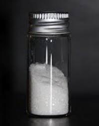
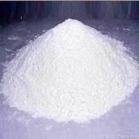
EDTA Disodium salt extra pure is a high-purity, laboratory-grade reagent used for the chelation (binding) of metal ions in analytical, biochemical, and industrial applications. It is commonly supplied as a white crystalline powder and is highly soluble in water.
Specifications and Properties
Chemical Name: Ethylenediaminetetraacetic acid disodium salt dihydrate
Formula: C₁₀H₁₄N₂Na₂O₈·2H₂O
Purity: ≥99–99.5% (extra pure grade)
Appearance: White, odorless crystalline powder
pH (5% solution in water): 4–5
Solubility: 100 g/L at 20 °C in water
Typical contaminants: Very low levels of heavy metals and insoluble matter; max 0.001% Pb, max 0.0001% As
Melting point: ~248 °C (with decomposition)
CAS Number: 6381-92-6
Common Uses
Buffer and reagent preparation in molecular biology, genetics, and biochemistry for chelating metals and protecting biomolecules.
Standard titrant in complexometric analysis for the quantitative determination of metal ions (e.g., Ca²⁺, Mg²⁺).
Water treatment, cleaning, and food preservation as a sequestering agent.
EDTA Disodium salt extra pure is favored for critical laboratory uses due to its high purity, minimal contaminants, and strong chelating ability
EDTA Disodium Salt 5% Solution is an aqueous preparation containing 5 grams of EDTA disodium salt per 100 milliliters of water. It is commonly used as a chelating agent in clinical, research, and industrial applications to sequester divalent and trivalent metal ions.
Properties
Composition: 5% w/v (5 g per 100 ml water).
Appearance: Clear, colorless solution; soluble in water; derived from a white crystalline solid.
pH of 5% Solution: 4.0 to 6.0 (acidic).
Chelation Value: 260–290 mg CaCO₃ per gram (typical for high-purity disodium EDTA salt).
Common Uses
Hematology: Used as an anticoagulant in blood collection tubes to prevent clotting by binding calcium.
Laboratory: Chelates metal ions in buffers, enzyme preparations, and nucleic acid isolation protocols.
Industrial: Added to water systems or cleaning solutions to bind calcium, magnesium, iron, and other metals.
Conservation: Removes rust and stains from stone, wood, and fresco surfaces by complexing metallic ions.
5% EDTA Disodium Salt Solution is valued for its strong metal-binding ability and is used in numerous fields for sample stabilization, protein and DNA preservation, and removal of unwanted metallic contaminants
EDTA Disodium Salt 5% Solution is an aqueous preparation containing 5 grams of EDTA disodium salt per 100 milliliters of water. It is commonly used as a chelating agent in clinical, research, and industrial applications to sequester divalent and trivalent metal ions.
Properties
Composition: 5% w/v (5 g per 100 ml water).
Appearance: Clear, colorless solution; soluble in water; derived from a white crystalline solid.
pH of 5% Solution: 4.0 to 6.0 (acidic).
Chelation Value: 260–290 mg CaCO₃ per gram (typical for high-purity disodium EDTA salt).
Common Uses
Hematology: Used as an anticoagulant in blood collection tubes to prevent clotting by binding calcium.
Laboratory: Chelates metal ions in buffers, enzyme preparations, and nucleic acid isolation protocols.
Industrial: Added to water systems or cleaning solutions to bind calcium, magnesium, iron, and other metals.
Conservation: Removes rust and stains from stone, wood, and fresco surfaces by complexing metallic ions.
5% EDTA Disodium Salt Solution is valued for its strong metal-binding ability and is used in numerous fields for sample stabilization, protein and DNA preservation, and removal of unwanted metallic contaminants.
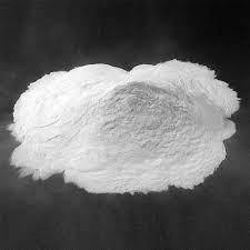
EDTA acid salt extra pure, also known simply as EDTA (ethylenediaminetetraacetic acid), is a high-purity laboratory reagent used for its powerful chelating ability with metal ions in a variety of analytical and industrial applications.
Specifications and Properties
Chemical Name: Ethylenediaminetetraacetic acid (EDTA)
Formula: C₁₀H₁₆N₂O₈
CAS Number: 60-00-4
Appearance: White, odorless crystalline powder
Purity: ≥99% (extra pure grade)
Solubility: Slightly soluble in cold water, more soluble in hot water and alkaline solutions (like NaOH, NH₄OH)
pH (5% solution): Typically 4–6
Chelation value: ≥339 mg CaCO₃/g
Heavy metals: Pb ≤ 0.001%, Fe ≤ 0.001%
Common Uses
Chelating agent for removing heavy metals and controlling metal ion concentrations in analytical chemistry, molecular biology, water treatment, and pharmaceutical formulations.
Binds divalent and trivalent cations (e.g., Ca²⁺, Fe³⁺, Mg²⁺) to form stable, water-soluble complexes, even at near-neutral pH.
Used in preparing metal-free buffers for enzyme studies, protein, and nucleic acid work.
Effective in scale removal, cleaning, and preservative systems.
EDTA acid salt extra pure is preferred when the highest levels of purity and the strongest chelating action are required, providing reliable results in sensitive laboratory, industrial, and clinical workflows.